
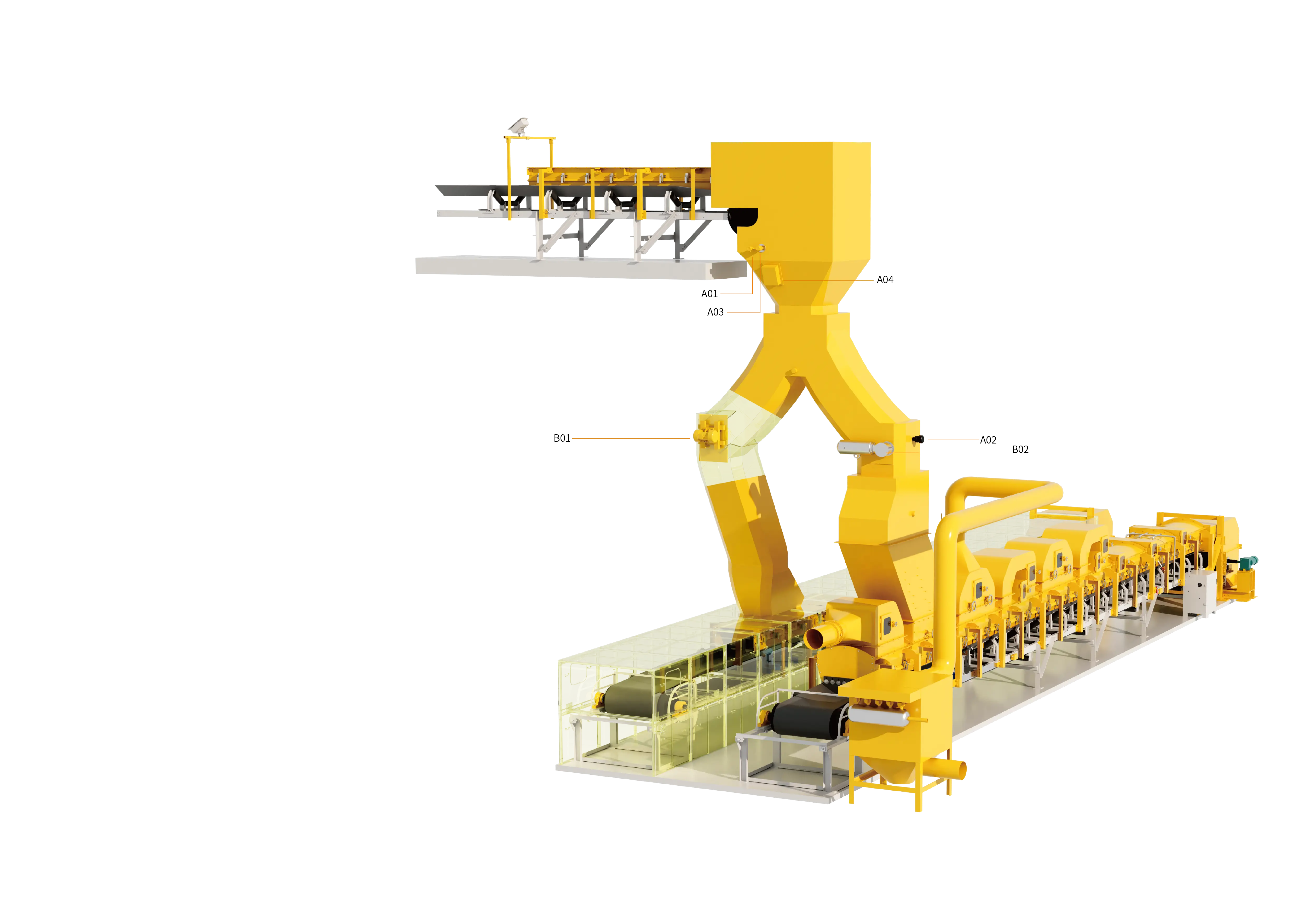
In continuous heavy-industry production such as mining and mineral processing, thermal power generation, cement and building materials, metallurgy and chemicals, and bulk cargo handling at ports, raw coal, ore, limestone, clinker and various granular and powdery materials must frequently pass through silos (Silo/Bunker), hoppers (Hopper) and belt conveyor transfer chutes (Transfer Chute) for storage and cross-line transfer. However, because the physical properties of bulk materials are complex and variable, material accumulation, wall adhesion, arching and even complete blockage occur very easily at silo discharge outlets and inside transfer chutes.
Once a silo or chute is blocked, the consequences range from interrupted downstream feeding and reduced-load operation of the main production line, to material overflow spreading at the transfer point, burial of the upstream belt conveyor head and motor stalling, which can then induce severe belt slippage, frictional ignition and even longitudinal tearing. In addition, relying on manual hammering of the silo wall or entering a confined space to poke the material free involves high labour intensity, long downtime, and extremely high risks of collapse burial and falling from height. Therefore, a thorough understanding of the physical causes of bulk material blockage, combined with a comprehensive management system that integrates "online condition sensing + active flow-assisting unblocking + automatic closed-loop interlocking", is the key for modern industrial bulk material storage and conveying systems to achieve intrinsic safety and unmanned, highly efficient operation.
1. Four Typical Blockage Patterns of Silos and Transfer Chutes and Their Physical Causes
Under gravity, the flow of bulk material is not a simple fluid motion, but a complex mechanical process governed jointly by internal friction between particles, external friction between particles and the wall, the surface tension of moisture, and impact compaction stress. In industrial plants, silo and chute blockages mainly manifest in the following four typical forms:
1. Mechanical interlocking and cohesive arching (Arching / Bridging)
When large irregular ore lumps or raw coal converge in the converging section of the silo cone, the particles press against each other and interlock geometrically to form a mechanically stable arch capable of bearing the weight of the material above (a mechanical arch). For fine powdery or high-moisture materials (such as wet coal slime and clayey mineral powder), the capillary forces and van der Waals forces generated by the liquid film on the particle surface bind the material into agglomerates, forming a strong "cohesive equilibrium arch" above the discharge outlet, which completely cuts off the flow below.
2. Ratholing
When the designed half-angle of the silo is too large or the material is extremely adhesive, the material around the silo wall consolidates and remains motionless for long periods, and only the central columnar area directly above the discharge outlet can discharge normally, forming a vertical hole penetrating the material bed (a "rathole"). The ratholing effect not only reduces the effective live capacity of the silo by more than 60%, but also, when the surrounding consolidated material suddenly collapses over a large area under temperature or humidity changes, it can very easily destroy the feeder below in an instant or completely block the transfer chute.
3. Wall adhesion and layered build-up at chute turning points (Wall Adhesion & Build-up)
In high-drop transfer chutes of belt conveyors, fast-falling wet and sticky material directly impacts the chute bottom plate and the impact-side wall. Under enormous normal impact force, the moisture in the material is squeezed towards the metal wall surface, forming a highly adhesive boundary layer. As operating time accumulates, the adhered layer thickens layer by layer like a rolling snowball, continuously reducing the effective flow cross-section of the chute until it develops into a full-section blockage.
4. Oversize jamming and back-filling (Oversize Jamming & Back-filling)
When overlong anchor bolts, wooden blocks or oversized gangue are mixed into raw coal or ore, mechanical jamming very easily occurs at the chute bifurcation (three-way flap gate) or at the discharge outlet of the guide chute. At the same time, if downstream conveying equipment stops due to a fault and the upstream is not interlocked and de-energised in time, the material will fill the entire transfer chute within seconds and back up to the upstream pulley.
2. Multi-dimensional Online Monitoring Technology for Blockage Conditions (Anti-Clogging Sensing Layer)
To "prevent trouble before it happens and clear blockages at an early stage", the material condition at the transfer chute and the silo throat must first be sensed accurately around the clock. Modern intelligent anti-clogging systems usually configure four types of core detection units according to the characteristics of the working conditions:
1. Microwave non-contact blockage detection unit
Microwave blockage detectors are installed in a through-beam arrangement of transmitter and receiver, forming a microwave monitoring beam across the blockage-prone section of the silo neck or transfer chute.
- Working mechanism: when material falls normally and smoothly, the material stream is in a discrete state and the microwave signal can pass through normally; once wall build-up or retention occurs inside, the high-density accumulated material layer blocks the microwave beam, and the receiver immediately outputs an alarm switching signal after a set delay.
- Technical advantages: the probe does not penetrate into the material stream, completely avoiding impact damage from large ore lumps and probe wear; moreover, microwaves have a very strong ability to penetrate dust, water mist and thin layers of adhered scale, making them highly suitable for harsh transfer station environments with heavy dust and high humidity.
2. Tilting-pressure (flap-gate) mechanical blockage detection unit
Tilting-pressure (or movable flap-gate) blockage detectors are installed at openings in the side wall of the chute that are not directly struck by normally falling material.
- Working mechanism: when blockage occurs inside the chute, the continuously accumulating material exerts a lateral squeezing thrust on the side wall, pushing the detector's movable pressure-bearing flap or tilting probe outward. When the deflection angle or pressure reaches a preset threshold, the internal micro-switch is triggered to output several independent dry-contact signals; after the accumulated material is cleared and falls away, the movable flap automatically resets by gravity or by a spring mechanism.
- Technical advantages: the mechanical structure is intuitive and reliable with extremely strong resistance to electromagnetic interference; it can be used not only for interlocked shutdown, but also directly as a trigger switch to start external rapping and clearing devices.
3. Rotary (paddle) blockage detection unit
The rotary detection unit uses a small motor to drive a stainless steel paddle extending into the silo to rotate slowly. When accumulated material rises and submerges the paddle, the paddle is obstructed and stops rotating; the internal torque detection mechanism then cuts off the motor power and outputs a material-jam signal; when the material is discharged, the paddle resumes free rotation. This method is widely used for high/low level and full-silo blockage monitoring in power plant raw coal bunkers, cement raw meal silos and chemical powder hoppers.
4. Coordinated detection of upstream and downstream material flow status
A single level detection point in the chute often lags behind reality. By configuring material status detection units on the upstream and downstream belt conveyors (such as contact or non-contact material flow detectors), the system can compare in real time whether "material is being fed in upstream" and whether "material is being discharged downstream". If the upstream continues to feed at full load while the downstream suddenly has no material flow, the system can predict the jamming risk in advance before the chute is completely filled.
3. Active Unblocking and Physical Flow-Assisting Technology System (Clearing Execution Layer)
Once the detection unit captures an early accumulation or arching signal, efficient and non-destructive physical flow-assisting measures must be used to break the static equilibrium of the material. Current mainstream engineering clearing solutions cover two dimensions: active external-force arch breaking and passive structural optimisation:
1. High-frequency vibration clearing unit (flexible wall breaking and friction-reducing flow assistance)
High-frequency vibration clearing devices are fixed to the outer wall of the transfer chute or to the rigid stiffening ribs of the silo cone.
- Mechanism of action: through high-frequency, small-amplitude periodic mechanical vibration, alternating shear stress is generated at the interface between the metal silo wall and the adhered material, instantly destroying the adhesion boundary layer formed by the surface tension of moisture, converting the static friction coefficient between material and wall into a very low kinetic friction coefficient, and thereby causing the adhered material to slide down smoothly.
- Applicable limits: highly effective for early-stage wall adhesion and slight arching of high-moisture fine-particle materials. However, engineering applications must strictly follow the principle of "no vibration with the gate closed" — that is, when the silo bottom gate is closed or the downstream belt is stopped, the vibrator must never be started, otherwise the vibration will actually compact the material in the silo further.
2. High-pressure air pulse clearing unit (powerful arch breaking and elimination of dead zones)
For stubborn mechanical interlocking arches, long-span cohesive arches and severe ratholing, high-frequency vibration often lacks sufficient energy; in this case, high-pressure air clearing units (commonly called air cannons or pneumatic arch breakers) must be installed.
- Mechanism of action: compressed air at 0.4–0.8 MPa stored in an air receiver is released instantly through a quick-exhaust solenoid valve within milliseconds of receiving a clearing command. The high-pressure air jet is directed through a directional nozzle straight into the arching dead zone of the silo or the turning point of the chute, generating a strong shock wave and gas expansion shear force that instantly shatters the equilibrium arch structure and restores gravity flow.
- Layout strategy: units are usually arranged in a spiral, layered pattern along the silo cone section or around the corners of large chutes, so that sequential pulse injection at multiple points achieves full-section clearing with no dead zones.
3. Passive anti-clogging design: fluidised chute reconstruction and low-friction liners
In addition to active clearing equipment, source-level structural optimisation is equally indispensable:
- Fluidised curved chute design: the discrete element method (DEM) is used to simulate material trajectories, converting traditional right-angle polyline chutes into smoothly transitioning spoon-shaped or parabolic curved chutes that guide the material to converge and fall centrally, eliminating high-speed vertical impact and vortex dead zones.
- High-performance anti-stick wear-resistant liners: ultra-high molecular weight polyethylene (UHMWPE) liners, microcrystalline zirconia-corundum ceramics or ceramic-rubber composite liners are laid on the impact face of the chute and the silo cone, using their extremely low surface energy (hydrophobicity) and high smoothness to reduce the probability of material adhesion at the source.
4. Graded Closed-Loop Control Logic of the Intelligent Anti-Clogging and Material Flow-Assisting System
By connecting the "blockage detection units (Group A)" and "blockage clearing units (Group B)" to the site PLC or centralised control system, an unattended three-stage progressive intelligent anti-clogging closed loop can be built:
- Stage 1: Preventive intermittent flow assistance (high-humidity mode) During the rainy season or when conveying highly viscous coal slime and mineral powder, the system can, based on the upstream material flow status signal and on the premise that the downstream belt is confirmed to be running normally, control the high-pressure air clearing unit or the high-frequency vibration unit to perform a short-pulse preventive sweep at a set cycle (for example, every 15–30 minutes), preventing the accumulation of adhered material layers.
- Stage 2: Online automatic clearing of light accumulation (self-healing without shutdown) When the primary blockage detector installed at the lower part of the chute (about 1/3 of the height from the bottom, or the microwave pre-warning position) detects a local retention signal, the PLC immediately triggers an audible and visual pre-alarm and automatically starts the vibration clearing device and the high-pressure air pulse unit in the corresponding area for combined clearing. At this stage the conveying system keeps running continuously, achieving "online self-healing without shutdown".
- Stage 3: Safety interlock emergency stop for severe blockage (equipment protection bottom line) If, because of jamming by oversized foreign objects, the accumulated material continues to rise after online clearing and triggers the upper secondary blockage detector (about 2/3 of the height from the bottom), or if the lower-level signal continuously times out and does not reset, the PLC will immediately determine a severe blockage fault and instantly output the highest-priority interlock command — first cutting off the power supply of the upstream feeder and the incoming belt conveyor, and simultaneously stopping vibration and air pulse operation, to prevent material overflow and equipment burial as well as belt tearing accidents.
5. Selection Comparison Table of Anti-Clogging Solutions for Typical Industrial Working Conditions
Given the differences in the physical properties of bulk materials in different industries, engineering selection should adopt differentiated combinations of monitoring and clearing strategies:
| Typical application scenario | Core material characteristics and blockage type | Recommended detection unit configuration | Recommended clearing and flow-assisting configuration |
|---|---|---|---|
| Coal preparation plant / thermal power plant coal handling transfer station | High moisture, highly viscous coal slime; very prone to wall adhesion at chute turning points and arching in raw coal bunkers | Microwave blockage detection unit + tilting-pressure (flap-gate) two-stage detection | High-frequency vibration clearing unit + low-friction polymer liners + air pulse at key dead zones |
| Metal mine primary crushing / ore transfer chute | Large lump size, high density, extremely strong impact; prone to mechanical jamming by large lumps | Heavy-duty tilting-pressure detector (with anti-impact baffle) + microwave through-beam monitoring | High-energy high-pressure air clearing unit + wear-resistant ceramic composite liners + curved chute optimisation |
| Cement plant raw meal silo / clinker powder hopper | Very fine particle size, easy to absorb moisture and cake, prone to severe ratholing and uneven fluidisation | Rotary (paddle) blockage detection unit + material status detection | Multi-layer array high-pressure air pulse arch breaking + high-frequency small-amplitude flow-assisting vibration on the silo wall |
| Port bulk terminal / open-air loading hopper | Extremely large throughput, strongly affected by rain and sea-salt fog; prone to sudden material surges and congestion | IP67 high-protection microwave detection unit + upstream/downstream material flow interlock monitoring | Dual-redundant high-frequency vibration clearing + automatic graded flow-limiting feed interlock control |
6. On-Site Installation, Commissioning and Safety Maintenance Management Specifications
To ensure that the anti-clogging and flow-assisting system delivers stable performance over the long term, on-site engineering implementation and daily maintenance must follow these guidelines:
- Impact-resistant and false-alarm-free installation of detectors: Contact-type detectors (such as flap-gate, tilting-pressure or rotary types) should be installed at side-wall positions that avoid direct impact from the main material stream, and an inclined anti-impact protective plate should be welded 100–200 mm above the probe; the wave-transparent window of microwave detectors should be made of wear-resistant PTFE or ceramic material, and the through-beam coaxiality must be maintained.
- Structural reinforcement of clearing equipment: High-frequency vibration clearing devices must never be welded directly onto the thin single-layer chute skin; they must be installed through channel-steel stiffening ribs or a rigid base frame, to prevent long-term vibration from causing fatigue cracking of the chute welds; high-pressure air clearing pipelines must be fitted with check valves to prevent high-dust hot gas from flowing back and damaging the solenoid valves.
- Strictly observe the safety red line of clearing operations: When the system suffers a severe blockage shutdown and automatic clearing is ineffective so that manual intervention becomes necessary, the power-off, tagging and lockout (LOTO) procedure must be strictly implemented. Maintenance personnel are absolutely forbidden to look upward from the bottom outlet of the silo or chute, or to enter the space below the silo to poke the material; they must work from top to bottom using long-handled tools through the upper inspection opening or a dedicated side poking hole, completely eliminating casualties caused by the sudden collapse of accumulated material.
By deeply integrating highly reliable online blockage detection technology with scientific physical arch-breaking and flow-assisting devices, enterprises can not only completely escape the crude maintenance mode of "hammering the silo and digging out material during shutdown", but also significantly improve the automation level and overall operational efficiency of continuous bulk conveying systems.
Learn about the intelligent anti-clogging and material flow-assisting system solution