
Chapter 1: Safety Hazards of Belt Conveyors in High-risk Industrial Scenarios and Emergency Stop Protection
In heavy industries such as underground coal mining, coal preparation plants, coal conveying systems of power stations, petrochemical storage, metallurgical coking and bulk cargo terminals, belt conveyors carry the task of continuous high-load transport of bulk materials. Because conveyor routes are usually hundreds of metres or even several kilometres long and the equipment along the line is filled with high-speed rotating pulleys and idlers, the on-site production environment is extremely complex.
During daily operation, a conveyor can easily trigger a major safety accident due to sudden conditions such as material jamming, belt tearing, abnormal equipment noise, personnel accidentally entering a hazardous area or mechanical failure. Especially in coal mines and chemical plants where methane explosive gas or high concentrations of combustible dust exist, sparks or high temperatures caused by equipment failure can very easily lead to catastrophic explosion and fire accidents.
In order to protect the personal safety of on-site operators and prevent equipment damage from spreading, national industrial safety standards mandate that highly reliable emergency shutdown devices - explosion-proof bi-directional cable pull switches (Explosion-proof Cable Pull Emergency Stop Switch) - must be installed on both sides along the entire length of the conveyor. As a "safety lifeline" that can be actuated at any point along the line, the device can cut off the motor power supply instantly in an emergency, providing a solid safety barrier for continuous conveying operations in flammable and explosive environments.
Chapter 2: Working Principle and Trigger Response Mechanism of the Explosion-proof Bi-directional Cable Pull Switch
2.1 Mechanical Transmission and Micro Switch Actuation Logic
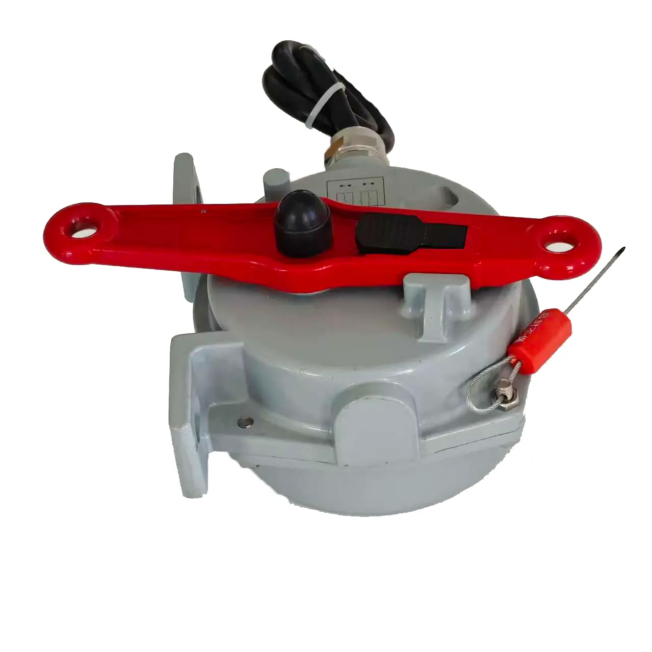
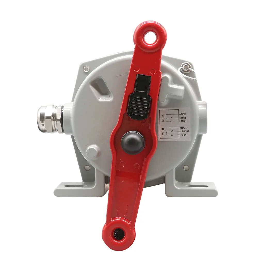
The explosion-proof bi-directional cable pull switch is a flameproof safety protection device installed in pairs on both sides of the conveyor frame. A steel wire rope extending along the conveyor line is connected to each of its left and right sides. Its core working principle is as follows:
- Normal standby state: when there is no external pulling force, the trigger lever of the pull switch remains in the vertical balanced position and the internal micro switch contacts stay in their normal working state (normally open / normally closed).
- Emergency pull cord action: when an emergency occurs in any area along the conveyor, on-site personnel pull the steel wire rope, and the pulling force acts on the rotary lever of the switch through the rope sleeve.
- Bi-directional triggering and circuit cut-off: when the lever deflects to the left or to the right and reaches the set actuation angle, the cam mechanism inside the switch instantly pushes the explosion-proof micro switch, outputs an interlocked shutdown signal and breaks the main motor control circuit, so that the conveyor stops running quickly.
- Self-locking and manual reset: the explosion-proof pull switch has a mechanical self-locking function. After an emergency stop action is completed, the lever is locked in the alarm position to prevent accidental restart of the equipment when the rope is released; the equipment can only return to the normal standby state after the on-site inspection personnel have eliminated the fault and manually pressed or rotated the reset handle.
2.2 Flameproof Structure and Environmental Adaptability
- High-strength explosion-proof enclosure: the enclosure is made of cast aluminium alloy or precision cast steel, and the precise flameproof joint surface design fully isolates the electric sparks that may be generated by the internal micro switch during actuation, preventing ignition of the external explosive gas atmosphere.
- High protection rating design: strong water-proof and dust-proof capability (protection rating up to IP65/IP67) effectively resists dust erosion and high-pressure water flushing in harsh industrial sites.
Chapter 3: Core Technical Parameters and Selection Guide
To help electrical engineers and equipment procurement teams make accurate selections, the following table summarises the core technical parameter specifications of the explosion-proof bi-directional cable pull switch:
| Technical Parameter | Specification and Performance Description |
|---|---|
| Product Name | Explosion-proof Bi-directional Cable Pull Switch / Explosion-proof Emergency Stop Switch (Explosion-proof Cable Pull Switch) |
| Explosion-proof Marking | Exd I Mb (for underground coal mines) / Exd II BT4/CT6 Gb (explosion protection for chemical gases) |
| Ambient Temperature | -20°C to +50°C |
| Relative Humidity | 0% – 95% RH |
| Atmospheric Pressure | 80 kPa – 110 kPa |
| Contact Quantity and Form | Multiple groups of independent SPDT (single-pole double-throw) normally open / normally closed contacts |
| Contact Capacity | AC 380V / 3A, DC 24V / 3A |
| Actuating Force Range | 40N – 70N (moderate operation to prevent false triggering) |
| Reset Method | Manual Reset |
| Applicable Cable Diameter | 6 mm – 10 mm diameter incoming cable |
3.1 Core Performance Advantages of the Product
- Bi-directional protection: a single switch simultaneously monitors the steel wire rope tension on both the left and right sides, greatly reducing the number of devices required along the line and saving wiring costs.
- Safe self-locking: the mandatory manual reset mechanism ensures that the machine can never be restarted by mistake before the accident has been eliminated, in compliance with the highest-level industrial safety regulations.
Chapter 4: On-site Installation Specifications and Engineering Commissioning of the Explosion-proof Cable Pull Switch
4.1 Installation Layout and Quantity Configuration
- Installation spacing: on the frames on both sides of the belt conveyor, one group of explosion-proof pull switches is generally installed in pairs every 30 to 40 metres.
- Steel wire rope fixing: between two pull switches, a rope support ring or support eye bolt must be installed every 3 metres to carry the dead weight of the steel wire rope and prevent excessive sagging of the rope from causing false actuation of the switch.
- Rope tension adjustment: the steel wire rope should be installed with moderate tightness, and a turnbuckle should be used to balance the tension on both sides so that the lever remains vertical when no external force is applied.
4.2 Mechanical Fixation and Electrical Interlock Commissioning
- Bracket welding / bolt fixing: the mounting bracket of the pull switch must be firmly welded or fixed to the conveyor stringer with high-strength bolts to prevent the installation from loosening due to frame vibration.
- Pull test: pull the steel wire rope forcefully at any position along the line and observe whether the lever of the pull switch deflects sensitively and triggers the shutdown signal.
- Signal response verification: check the PLC/DCS centralised control system in the control room to confirm that the emergency stop signal is transmitted accurately, that the main motor power supply is cut off instantly, and that the equipment cannot be restarted a second time before manual reset.
Chapter 5: Electrical Wiring Safety, Daily Maintenance and Troubleshooting Guide
5.1 Electrical Wiring and Explosion-proof Safety Warnings
- Opening the cover with power on is strictly prohibited: underground or in explosion-proof areas, any maintenance and wiring work must be carried out after the upstream power supply has been completely cut off; opening the explosion-proof enclosure with power on is strictly forbidden.
- Tighten the cable entry device: the incoming cable must pass through the explosion-proof sealing ring and the metal washer, and the compression nut must be fully tightened to ensure explosion-proof sealing; the applicable cable outer diameter is 6~10 mm.
- Terminal verification: according to the terminal diagram inside the switch, connect the normally closed contacts in series into the control circuit to ensure that pulling the rope immediately breaks the circuit.
5.2 Daily Inspection and Maintenance Specifications
- Remove accumulated dust and material: regularly clean the coal dust, dust and material accumulation around the switch enclosure and the rotating lever to prevent the mechanical transmission parts from jamming.
- Check the condition of the steel wire rope: regularly inspect the steel wire rope along the line for broken wires, corrosion or slackness to ensure smooth force transmission when the emergency rope is pulled.
- Inspection of flameproof surfaces and sealing rings: regularly check whether the flameproof joint surfaces are scratched or corroded, and check the ageing of the rubber sealing rings and replace them in time to ensure that the flameproof protection performance remains effective over the long term.